Pop Bumper LEDs

Remember those Adafruit LED boards I stuck in the pop bumpers? Since this is a DIY project, I figured I’d do these myself too. I’ve designed and ordered PCBs from China, including assembly and surface-mount soldering. It’s really not a terrible price for 10 boards, though I could do way better if I solder on my own. Maybe I’ll do both, and sell a few to my DIY friends?

Leg Brackets

I put the leg brackets on and ordered a few parts I didn’t realize I was missing (why do they sell the legs separate from the feet/levelers?). They’re on now, and the backbox is fully assembled and glued together. I’m going to set it up and start moving my hardware to the new cabinet soon. Also on the list: installing the coin door and lockdown bar retainer.

Flogging a Dead Horse?

Nope, I’m gonna ride that sucker dead or alive.

Building a fence

I had to build a fence to use the cutter blade for the plastic channel that holds the glass on the cabinet. This would have been way easier before I put the cabinet together.

Plastic glass channel
Corner holes

And here I am drilling holes into the corners of the cabinet where the legs will attach. This would be nearly impossible without that little drill guide, which has a 90 degree notch on the back that lets you hold it securely while you drill into an outside corner.

That C14 power socket? Yeah, the internal leg support covers half of it. Maybe I’ll put something else there. Or notch the support bracket and keep the power there.

More cabinet pics!

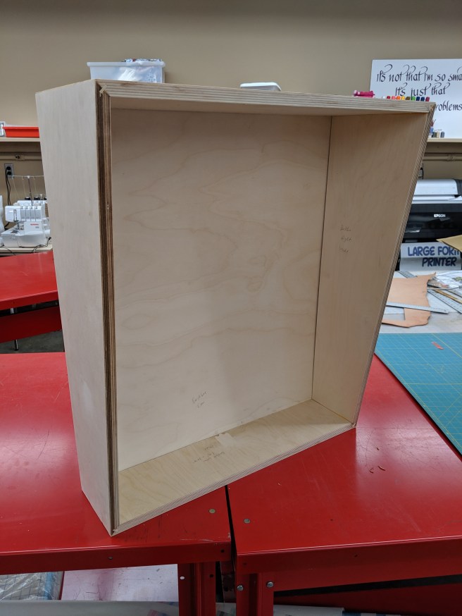
Last night I glued up the main cabinet! The backbox was done a few days ago. It took a couple of extra hands, but it’s all together now.

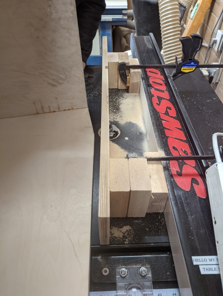
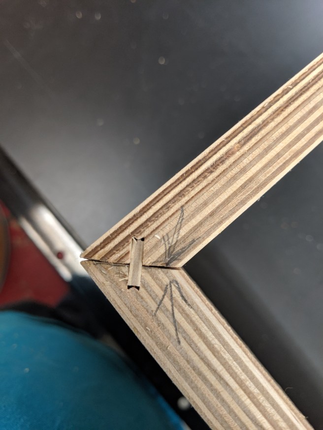
I abandoned the lock miter joint due to its complexity. I’m not a professional cabinet maker, and the chance that I mess up one cut out of sixteen was pretty good and would increase my materials cost by 50% (about $90 for this nice 3/4″ Baltic birch plywood). So I went with a spline joint that could easily be cut on the table saw.

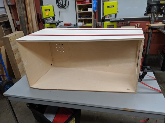
The nine 1″ holes in the bottom of the cabinet are where the down-firing subwoofer will be located. The small cutout near them is for a C14 power socket.

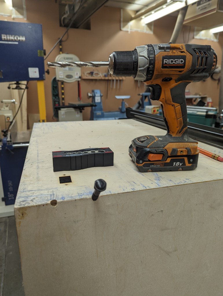
My next few steps include adding the leg braces and drilling holes for leg bolts, priming and painting, and attaching the backbox to the main cabinet.

Cabinet Progress!

Last night I test-fitted the front panel with the coin door and plunger, and despite a small issue with the plunger (easily solved with a 1/2″ drill bit) everything fit great!

The way the coin door fits is very satisfying, I love me some clean CNC work.

Yeah I Know…

It’s been forever since I’ve posted. Honestly I’ve been dragging my feet because I need a deeper, more modern cabinet to support a second level area and ramps, etc. What I have been using just won’t work, and it’s very hard to design a game that will use those without a cabinet that supports them. So I’ve been working on the CAD files to cut out what I need on the CNC router. I’ve cut out both cabinet sides as well as the backbox sides. The bottom, front, and back of the cabinet and the back of the backbox still need cut, but that’ll happen soon. Here’s proof:

mvimg_20190418_190046

You’ve Got To Start Somewhere

I installed the pop bumpers in a pretty much random spot. Cutting the holes by hand, even with a nice sharp Forstner bit, isn’t very fun. Next time it will all be CNC-cut. I also changed the lane guides by the flippers, installed some wire guides (not seen), and cut holes for some other playfield assemblies (also not seen). Progress is made!

img_20180627_194357

Pretty Pop Bumpers

I yanked the caveman technology incandescent bulb from the pop bumper mechanisms, and am replacing them with Adafruit Neopixel Jewels. They have 7 RGB LEDs that are serially addressable, and look so much better…

img_20180623_173750